


YGC-TBQ Solar Total Radiation Sensor
Brand: YIGU
Item: Research grade solar total radiation sensor
Application areas: Widely used in solar energy utilization, meteorology, agriculture, aging of building materials, and air pollution to measure solar radiation energy.
Item: Research grade solar total radiation sensor
Application areas: Widely used in solar energy utilization, meteorology, agriculture, aging of building materials, and air pollution to measure solar radiation energy.
WhatsApp: 8615271247832
Description
Product Introduction
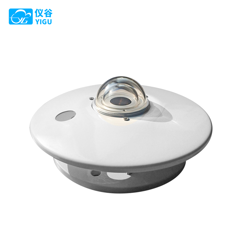
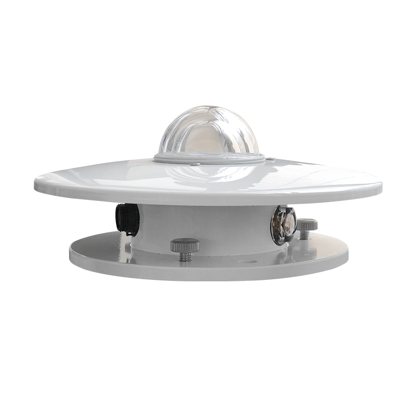
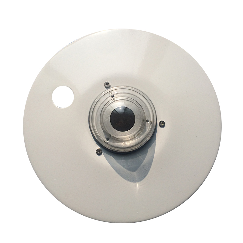
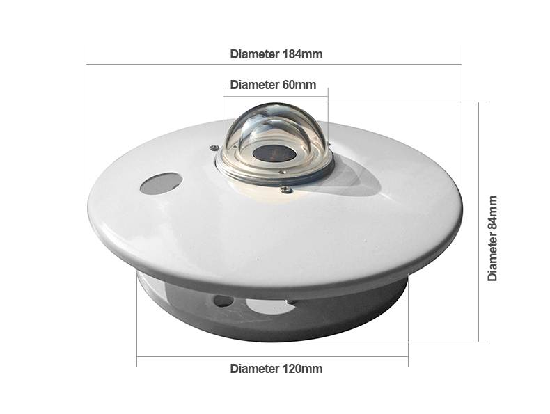
The YGC-TBQ Total Radiation Sensor operates on the principle of thermoelectric induction and, when used with various radiation recorders or radiation voltmeters, can accurately measure total solar radiation.
The core sensing element of this sensor is a multi-junction thermopile constructed using a wire-wound electroplating method, with its surface coated in a high-absorption black layer. The hot junctions are located on the sensing surface, and the cold junctions are housed inside the body of the device. The temperature difference between the hot and cold junctions generates a thermoelectric potential. Within the linear range, the output signal is proportional to the solar irradiance.
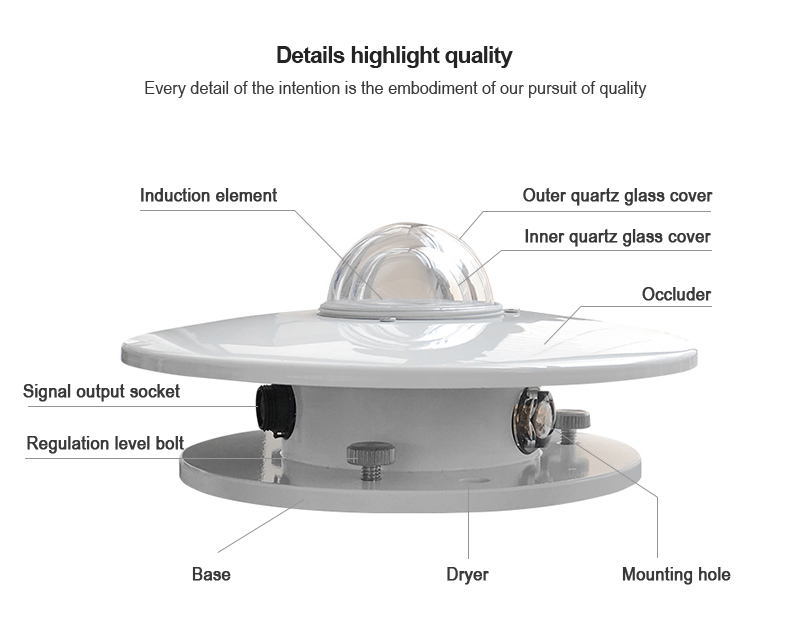
A double-layer glass cover is used to minimize the effect of air convection on the radiometer. The inner cover is designed to block the infrared radiation emitted by the outer cover itself.
This sensor is used to measure total solar radiation within the spectral range of 0.3–3μm. It can also measure solar radiation incident on inclined surfaces. By orienting the sensing surface downward, it can measure reflected radiation. With a shading ring, it can measure diffuse radiation. Therefore, the sensor is widely used in fields such as solar energy utilization, meteorology, agriculture, building material aging, and atmospheric pollution for measuring solar radiation energy.
Technical Specifications
| YGC-TBQ research grade solar total radiation sensor | ||||
| Power Supply | DC 5V | DC 9-30V | ||
| Output Signal | Current | 4~20mA | 0~20mA | |
| Current | 0~20mV | 0~2.5V | 0~5V | |
| Serial Port | RS485(□Default Modbus □ASCII) | RS232(□Default Modbus □ASCII) | ||
| Cable Length | □ Standard:2.5 meters | □ Other: | ||
| Spectral Range | 0.3-3μm | Sensitivity | 7~14μV▪㎡/W | |
| Measurement Range | 0~2000W/㎡ | Accuracy | ±3% | |
| Response Time | ≤35 seconds (99%response) | Resolution | 1W/㎡ | |
| Non-Linearity Error | ≤±3% | Internal Resistance | Approx 250Ω | |
| Tilt Response Error | ≤±5% | Spectral Selectivity | ≤±10% | |
| Azimuth Response Error | ≤±30W/㎡ | Temperature Error | ≤±8%(-40℃~+40℃) | |
| Weight | Approx 2.5kg | Annual Stability | ≤±3% | |
| Ambient Temperature | -40℃~+50℃; Relative humidity: 0% to 100% | |||
Product Assurance
Product Details
Product Dimensions
Installation and Wiring Methods
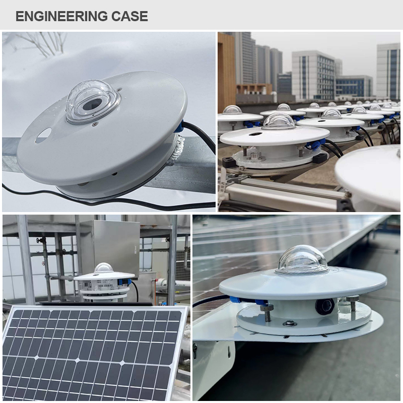
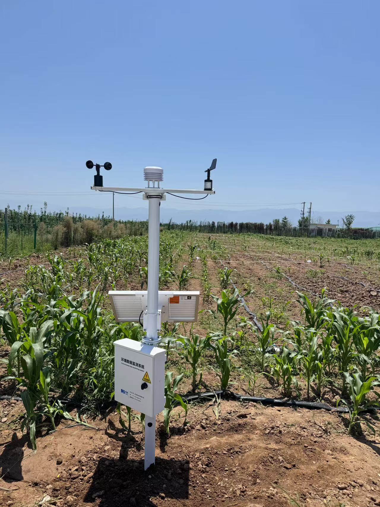
The sensor should be installed in an open area with no obstacles above the sensing surface. Then, adjust the radiometer to a level position, fix it securely, open the protective cover, and connect the total radiation meter output cable to the data acquisition equipment for observation.
(1)If the sensor is equipped with our company's instrument, directly use the sensor cable to connect the sensor to the corresponding interface on the instrument.
(2)If the sensor is purchased separately, the wire sequence is as follows:
|
Color |
Output Signal |
|||
|
Head |
Transmitter: Voltage/Current |
RS485 |
RS232 |
|
|
Red |
Signal Positive |
Power Positive |
Power Positive |
Power Positive |
|
Black |
Signal Negative |
Power Negative |
A+ |
Connect to PC RX Serial Port Pin 2 |
|
Yellow |
Signal Negative |
Signal |
B- |
Connect to PC TX Serial Port Pin 3 |
|
Green |
|
|
Power Negative |
Power Negative (Connect to PC Serial Port Pin 5) |
About Sensor Communication Protocol Selection
- If you are using a single sensor to connect directly to a computer to read data, it is recommended to use the company’s private protocol (see page 3). This allows data to be displayed intuitively in ASCII code (hex sending, non-hex receiving).
- If you are using multiple sensors interconnected to a PLC, SCADA, or programmable acquisition instrument, it is recommended to use the standard ModBus-RTU protocol (see page 2, hex sending and receiving).
Product Maintenance
- Be especially careful when opening or closing the protective cover, as the filter dome is precious and fragile. The filter dome must be kept clean and should be wiped regularly with a soft cloth or fur.
- Ensure no water enters the filter dome, and there should be no condensation inside the dome. Regularly check whether the desiccant inside the desiccator has become damp (turning from orange to dark). If so, replace it promptly or bake the desiccant in an oven until it turns back to orange before reusing it.
- During heavy rain (snow, ice, etc.) or extended periods of precipitation, to protect the radiometer, the observer should cover the sensor based on specific circumstances. Remove the cover after the rain stops.
- If the TBQ Total Radiation Sensor has been in use for over two years, its sensitivity must be recalibrated by the manufacturer or a metrology department.
Product Model Selection
|
Model |
Power Supply |
Output Signal |
Description |
|
YGC-TBQ - |
|
|
TBQ Total Radiation Sensor (Transmitter) |
|
|
5V- |
|
5V Power Supply |
|
KV- |
|
9-30V Power Supply |
|
|
|
VM |
0-20mV |
|
|
V2 |
0-2.5V |
||
|
V |
0-5V |
||
|
A1 |
4-20mA |
||
|
A2 |
0-20mA |
||
|
W1 |
RS232 |
||
|
W2 |
RS485 |
||
|
Example: YGC-TBQ -KV-A1; TBQ Total Radiation Sensor, 9-30V power supply, 4-20mA current signal output. |
|||
CONTACT US
📍Address:Room 301, Building 4, Gezhouba Sun City Industrial Park, East Lake High-Tech Development Zone, Wuhan, Hubei Province, China
📞Tel:+86 19522958500
📲WhatsApp:8615271247832
No Additional Information
Related products
Contact us
YIGU Sensors
Professional Weather Sensor & Weather Station Manufacturer
Telephone: +86-027-87915379
WhatsApp:+86 15271247832(Liang)
Email: info@whchenyun-tech.com
Address: Room 301, Building 4, Gezhouba Sun City Industrial Park, East Lake High-Tech Development Zone, Wuhan, Hubei Province, China
Get In Touch
Address
Room 301, Building 4, Gezhouba Sun City Industrial Park, East Lake High-Tech Development Zone, Wuhan, Hubei Province, China
Room 301, Building 4, Gezhouba Sun City Industrial Park, East Lake High-Tech Development Zone, Wuhan, Hubei Province, China
Phone
+86 19522958500
+86 19522958500
WhatsApp
+86 15271247832
+86 15271247832
SUBSCRIBE NEWSLETTER
- Get all the latest information on events, sales and offers. Sign up for newsletter:
Scan or click to chat

Scan to chat with us

Cloud Data
Scan to view cloud data
Copyrights © 2013-2026 Wuhan Chenyun Technology Co., Ltd. All rights reserved | Private Policy